8431-8432
-
特征
小尺寸
用于拉伸和压缩力
温度补偿从 -55 °C 开始,最高可达 200 °C 可选
灵敏度高
相对非线性:≤ ±0.15 % F.S.
测量范围从 0 ... 2.5 N 到 0 ... 100 kN
8432 型具有机械拉伸和压缩过载保护
burster自动校准TEDS功能 可选
-
产品数据
Model 8431, 8432 Measuring range 8431
0 … 5 N
0 … 10 N
0 … 20 N
0 … 50 N
0 … 100 N
0 … 200 N
0 … 500 N
0 … 1 kN
0 … 2 kN
0 … 5 kN
0 … 10 kN
0 … 20 kN
0 … 40 kN
0 … 50 kN
0 … 100 kN8432
0 … 2.5 N
0 … 5 N
0 … 10 N
0 … 20 N
0 … 50 N
0 … 100 N
0 … 200 N
0 … 500 N
0 … 1 kN
0 … 2 kNDirection of force Tension and compression Standardization Option Signal output 8431
15 … 40 mV/V
0.4 mV/V
0,5 mV/V
2 mV/V
depending on measuring range8432
15 … 40 mV/V
0.4 mV/V
0,5 mV/V
2 mV/V
depending on measuring rangeProtection class IP65 Overload protection 8431
No8432
YesPull-plate No Load introduction button No Range of operating temperature -55 ... +120 °C Specific characteristics - Small dimensions
- Temperature compensation starting at - 55 °C and up to 200 °C optional
- Minimum lateral sensitivity due to supporting membranes
- burster TEDS optionally available
-
说明
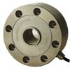
Precise tension and compression force measurements can be performed in limited space with model 8431 and 8432 precision miniature load cells. High precision, various measuring ranges, convenient load application via threaded pins with external winding and small dimensions offer a wide scope of applications in laboratories and production.
The series are among our most precise and yet mechanically sturdy miniature load cells. All options, typical only for larger load cells, are available with this miniature series such as hermetically sealed construction, overload protection and boring for pressure compensation when applied under vacuum.
Its complex design with integrated support membranes and overload protection reduces additional construction effort for external overload protection or guidance of force of applied parts in many applications. This requires little space, has little material and weight and almost no component friction, which could falsify the measurement result.
The connection cable suitable for robot applications make the precision miniature load cells especially suitable for use in the areas of special purpose- Machinery manufacture
- Tool manufacturing
- Handling gear
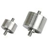
The force to be measured is applied to the cylindrical sensor unit in the tension or compression direction by means of the two external threads. This means that the sensor must be mounted without any attachments touching the end faces of the sensor housing. This avoids excessive contact pressures on the material and tensions inside the sensor that would affect its measuring element. Please refer to the sensor user manual for guidance on the various options for fitting the sensor, which depend amongst other factors on its measurement range. Although the precision miniature load cell is designed to isolate the measuring element from external forces, torsion and bending moments should be avoided.
Two stabilizing support diaphragms inside the sensors for small measurement ranges minimize the effect of transverse forces and moments and ensure long-term mechanical stability for measurements. The network for temperature compensation or standardization of the output signal is located on a sheathed circuit board in a wider section of the sensor's connecting cable. The maximum static operational force is the maximum force in the direction of the measurement axis that the sensor can tolerate. The overload protection is not designed for frequent use of the sensor in the overload range or for sudden loads. The sensors work in any orientation. They have an active side which acts directly on the measuring element, whereas the passive side is fixed to the housing.
-
产品介绍和下载
-
附件
-
视频
-
链接和CAD数据

相关产品